Search

Who is online?
In total there are 2 users online :: 0 Registered, 0 Hidden and 2 Guests None
Most users ever online was 301 on Thu 21 Oct 2021 - 11:24
Latest topics
» RC Submarine: Russian Akula Class by redboat219 Tue 27 Sep 2022 - 11:43
» Land Rover Defender D90 photos and details only (picture intensive!)
by babyboy Fri 25 Jun 2021 - 16:39
» [Offroad Bashing and Rally] Offroad Bashing and Rally at Tampines Track 12 Jan 2020 - 0900hrs
by boolean21 Sat 11 Jan 2020 - 10:15
» [Scale Trail] Woodgrove Ave - Sunday 20 Oct 2019 0900hrs
by boolean21 Sat 19 Oct 2019 - 16:31
» vHOBBY RC videos
by CraftRC Fri 21 Jun 2019 - 21:32
» Suzuki Samurai 3D Printted project
by CraftRC Sat 4 May 2019 - 18:39
» WTS : Redcat Gen 7 Pro
by staypuft Mon 7 Jan 2019 - 11:31
» Hello all! Dan here
by csd8888 Fri 5 Oct 2018 - 8:27
» [Offroad Trails] Offroading at Tampines Quarry 16 Sep 2018 - 0900hrs
by boolean21 Sat 15 Sep 2018 - 18:41
» [Scale Trail] Woodgrove Ave - Sunday 12 Aug 2018 0900hrs
by boolean21 Sat 11 Aug 2018 - 22:51
» [Trail and Bash!] Woodgrove Ave - Sunday 22 Jul 2018 0900hrs
by boolean21 Sat 21 Jul 2018 - 19:39
» [Scale Trail] Woodgrove Ave - Sunday 01 Jul 2018 0900hrs
by boolean21 Sat 30 Jun 2018 - 20:39
» wts hobbywing esc + motor
by kelvintan_hc Thu 28 Jun 2018 - 15:36
» Axial roll cage crash
by CraftRC Fri 1 Jun 2018 - 20:16
» Jeep cherokee XJ crawling
by CraftRC Sat 26 May 2018 - 21:54
» Jeep cherokee XJ crawling
by CraftRC Sat 26 May 2018 - 21:54
» Extreme Rock Crawler Axial Wraith
by CraftRC Tue 8 May 2018 - 17:35
» [Scale Trail] Woodgrove Ave - Sunday 06 May 2018 0900hrs
by boolean21 Sat 5 May 2018 - 17:14
» Cab Land Rover Defender
by CraftRC Fri 4 May 2018 - 17:41
» Cab Land Rover Defender
by CraftRC Fri 4 May 2018 - 17:41
Most active topic starters
| boolean21 | ||||
| RTECH | ||||
| gionata78 | ||||
| laneboysrc | ||||
| oceanic | ||||
| Marpek | ||||
| babyboy | ||||
| ShaiAX55 | ||||
| Wrigleys | ||||
| Holdencars |
Hello there New Member
2 posters
Page 1 of 1
 Hello there New Member
Hello guys, I am a new member here  just wanna say hi and yes I do have some problem and been seeking answers, that is how I ended up here.
Regards,
topper
Regards,
topper
topper- Crawler
- Posts : 9
Join date : 2017-07-17
 Re: Hello there New Member
Hello Werner,
Good afternoon, I am having issue with the controller of my Maisto Rock Crawler Extreme, it would go forward and reverse just fine, just not left and right, when I took the controller apart, I can see that the forward reverse is actuated via 2 buttons which gets depressed when I press the trigger.
It is a pistol grip remote control.
The problem I see is the left right steering. I can see on the PCB, there are 3 contacts leads, lets call it A, B and C. When the steering is turned left, A is pushed against B which makes it goes left, and when the steering is turned right, B and C gets pushed together. Problem thou, it seems something that is supposed to push them together is missing from in there, and I do not recall anything falling out....
So I guess I am here to see who have a similar model ( 27Mhz - 3 channels ). Whether they can be so kind as to take a photo of the steering mechanism, I do not seem to be able to find them anywhere, not even on ifixit etc.
Cheers.
topper- Crawler
- Posts : 9
Join date : 2017-07-17
 Re: Hello there New Member
It will be hard to find that exact model of transmitter. I guess you best bet will be to glue a piece of plastic, or use a screw, as actuator for the buttons.
 Re: Hello there New Member
laneboysrc I will try and post some photos tonight.
but your idea is sound, my only concern is whether screwing into the plastic will break it, anyways I will wait till I post some photos so you can let me know if the ideal is sound or not thanks for your attention, you are the only help I can get after asking and searching around for almost 6 months lol
but your idea is sound, my only concern is whether screwing into the plastic will break it, anyways I will wait till I post some photos so you can let me know if the ideal is sound or not
topper- Crawler
- Posts : 9
Join date : 2017-07-17
 Re: Hello there New Member
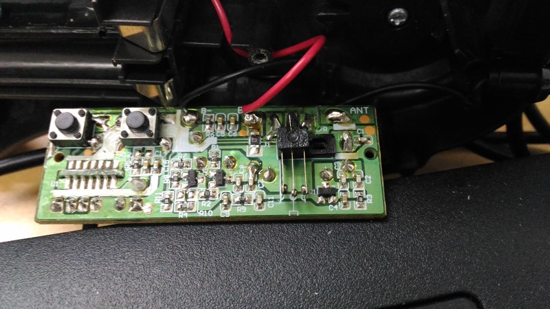
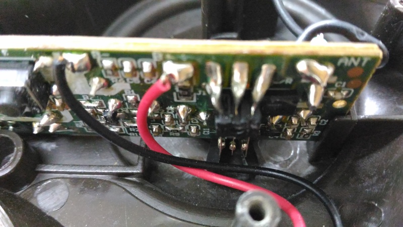
Hello laneboysrc, thanks for your PM, unfortunately I have not post enough to reply to you. Let me share some photos here, first here you can see the PCB board and the 3 contact leads I was talking about. If the left lead and center lead touches then it goes right, if right lead and center lead touches, then it goes left.
PCB Board

The leads are on the right side of the PCB.
PCB Board

The leads are on the right side of the PCB.
topper- Crawler
- Posts : 9
Join date : 2017-07-17
 Re: Hello there New Member
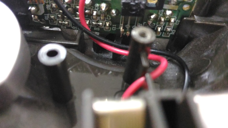
Here is a photo showing the alignment of the 3 lead to the steering inverse "V" mechanism...
Lead to steering inverse "V" alignment

Lead to steering inverse "V" alignment

topper- Crawler
- Posts : 9
Join date : 2017-07-17
 Re: Hello there New Member
Here I turn the steering on the controller to the left ( when holding it in the proper orientation, view now shows you looking from under the steering knob of the controller ).
Turning steering left on the controller

You can see a gap between the left most lead and the right side of the plastic, there is a height gap there and it is not moving those leads, also from this photo you can see how far the "legs" of the inverse "V" move... so some how something is missing here and i am trying to find out and I do not seem to find any online resource or photo of it.
Turning steering left on the controller

You can see a gap between the left most lead and the right side of the plastic, there is a height gap there and it is not moving those leads, also from this photo you can see how far the "legs" of the inverse "V" move... so some how something is missing here and i am trying to find out and I do not seem to find any online resource or photo of it.
topper- Crawler
- Posts : 9
Join date : 2017-07-17
 Re: Hello there New Member
Also if you see the photo when the steering has been turned left, the "V" travels by a lot, if I were to stick a tiny screw on each leg of the "V" it would have move the left lead too far into the right lead zone... which also lead me to think there must be something there but when I first opened the enclosure months ago I took note to make sure nothing fell out and there wasn't any lose pieces as far as I can tell...
topper- Crawler
- Posts : 9
Join date : 2017-07-17
 Re: Hello there New Member
Thanks for the photos!
If I am seeing it correctly, none of the switch contacts extend far enough down to get in contact with the inverse V, despite the PCB being seated correctly.
In theory there could be two ways the switch and inverse V operate:
- The edges of the V push the outer contacts of the switch to the middle contact
- The edges of the V push the middle switch contact to the outer contacts
Given how far the inverse V travels when you move the steering, I would say that the second scenario is the case: the inverse V is supposed to move the middle contact to either the left or right outer contact.
There may be a small piece gone missing that hooks onto the middle contact and extends down into the space between the inverse V.
If that is the case, then an easy fix would be to solder a stiff wire onto the middle switch contact that extends down into the inverse V, so that when the V moves it takes the middle with it and pushes it left/right.
 Re: Hello there New Member
Hello LaneBoys, great news, thanks for your insights, I have fixed the problem. It is so easy, no soldering of wire is required to extend the middle lead.
All I used was a cable tie. It has the perfect rigidity too. So what i did was use a cable tie, cut it to the right length so that I can bend one end (the short leg of the letter "L") into 90 degree. The long leg of the "L" goes into the inverse "V" because it is plastic and bendable it can form a curve when the "V" is centered and when you turn the steering to either extremities, the stretches enough and still stay inside the grove of the inverse "V"
On the short leg of the "L" I cut a slit down the middle so that the middle contact lead is sitting inside this slit, the short leg of the "L" is oriented such that it curves out from behind the middle lead and that was it.
The cable tie being flat was thin enough to also move and slide behind all 3 leads without interference.
So once again, thank you very much for that insight into how the mechanics of it should work, that was the critical information I need to move forward!
topper- Crawler
- Posts : 9
Join date : 2017-07-17
 Re: Hello there New Member
Here is a sketch of my solution, once I screwed it all in and tested it to be working fine, I just didn't wanna open it back up again lol....
The cable tie solution
The cable tie solution
topper- Crawler
- Posts : 9
Join date : 2017-07-17
 Re: Hello there New Member
Congrats, well done! Make sure you join the next outing, watch the board for announcements.
 Similar topics
» New Member Amerkulai from JB
» MIA member(missing in action)
» Brand spankin new member from Thailand
» MIA member(missing in action)
» Brand spankin new member from Thailand
Page 1 of 1
Permissions in this forum:
You cannot reply to topics in this forum

