


None
Most users ever online was 301 on Thu 21 Oct 2021 - 11:24
by redboat219 Tue 27 Sep 2022 - 11:43
» Land Rover Defender D90 photos and details only (picture intensive!)
by babyboy Fri 25 Jun 2021 - 16:39
» [Offroad Bashing and Rally] Offroad Bashing and Rally at Tampines Track 12 Jan 2020 - 0900hrs
by boolean21 Sat 11 Jan 2020 - 10:15
» [Scale Trail] Woodgrove Ave - Sunday 20 Oct 2019 0900hrs
by boolean21 Sat 19 Oct 2019 - 16:31
» vHOBBY RC videos
by CraftRC Fri 21 Jun 2019 - 21:32
» Suzuki Samurai 3D Printted project
by CraftRC Sat 4 May 2019 - 18:39
» WTS : Redcat Gen 7 Pro
by staypuft Mon 7 Jan 2019 - 11:31
» Hello all! Dan here
by csd8888 Fri 5 Oct 2018 - 8:27
» [Offroad Trails] Offroading at Tampines Quarry 16 Sep 2018 - 0900hrs
by boolean21 Sat 15 Sep 2018 - 18:41
» [Scale Trail] Woodgrove Ave - Sunday 12 Aug 2018 0900hrs
by boolean21 Sat 11 Aug 2018 - 22:51
» [Trail and Bash!] Woodgrove Ave - Sunday 22 Jul 2018 0900hrs
by boolean21 Sat 21 Jul 2018 - 19:39
» [Scale Trail] Woodgrove Ave - Sunday 01 Jul 2018 0900hrs
by boolean21 Sat 30 Jun 2018 - 20:39
» wts hobbywing esc + motor
by kelvintan_hc Thu 28 Jun 2018 - 15:36
» Axial roll cage crash
by CraftRC Fri 1 Jun 2018 - 20:16
» Jeep cherokee XJ crawling
by CraftRC Sat 26 May 2018 - 21:54
» Jeep cherokee XJ crawling
by CraftRC Sat 26 May 2018 - 21:54
» Extreme Rock Crawler Axial Wraith
by CraftRC Tue 8 May 2018 - 17:35
» [Scale Trail] Woodgrove Ave - Sunday 06 May 2018 0900hrs
by boolean21 Sat 5 May 2018 - 17:14
» Cab Land Rover Defender
by CraftRC Fri 4 May 2018 - 17:41
» Cab Land Rover Defender
by CraftRC Fri 4 May 2018 - 17:41
| boolean21 | ||||
| RTECH | ||||
| gionata78 | ||||
| laneboysrc | ||||
| oceanic | ||||
| Marpek | ||||
| babyboy | ||||
| ShaiAX55 | ||||
| Wrigleys | ||||
| Holdencars |

Laneboysrc - DIY Light controller system

Laneboysrc - DIY Light controller system
![]() by laneboysrc Tue 31 Jul 2012 - 20:42
by laneboysrc Tue 31 Jul 2012 - 20:42
First of all, I highly recommend NOT doing this. Total overkill, lots of fiddly jobs, and adding quite some complexity to a trailing vehicle -- which means it will be more prone to failure.
I did it anyway
Since one of my other hobbies long time ago was electronics, I decided to build a light controller system for our Dingo. I had a mad dash to the finish line last week until Saturday so that the car
is ready for the Sunday trail. Everything worked fine.
The light controller is about the size of a 3-channel receiver, albeit being made with 1990's technology -- my eye-sight is too bad already for SMD.

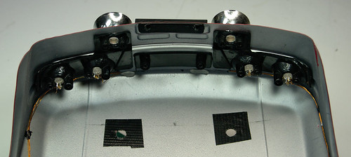
There are actually two units: one in the receiver box of the SCX10, and a "slave" unit in the body. A single servo extension cord links the two, so it is easy to take the body off.


In total there are now 20 LEDs in our Dingo: 6 in the bumpers, and 14 in the body. The LEDs in the body are wired up with 0.19 mm thin "enamel wire". The model railway guys use it a lot. It is isolated, but can be soldered as the isolation melts at 400 degrees. Allows for tiny wiring harnesses.
Right now the light controller can perform the following functions:
- Parking, Low-beam, Fog lamps and High-beam can be switched on/off using CH3
- Brake and Reverse lights are automatically controlled by monitoring the throttle channel
- Indicators only come on when you want to. You have to stay in neutral for 1 seconds, then hold the steering left/right for one second before they engage. This way normal driving does not trigger the indicators for more realism.
- Hazard lights can be switched on/off using CH3
- Programmable servo output designed to drive a steering wheel
I made a short video to show what it does.
(pardon my horrible speaking
 )
)More information, including links to the schematics and source code can be found on our blog at
http://laneboysrc.blogspot.sg/2012/07/diy-car-light-controller-for-3-channel.html
Next iteration: make a sound unit for my XR311...
cheers, Werner

laneboysrc- Crawler
- Posts : 877
Join date : 2012-05-21 -

Re: Laneboysrc - DIY Light controller system
![]() by boolean21 Tue 31 Jul 2012 - 20:58
by boolean21 Tue 31 Jul 2012 - 20:58
thanks for sharing the source code.
nice write up and your source code is well documented! i think every programmer loves to read these kind of work!
will look through your source code and see if i can adapt some for my future AVR project..

boolean21- Crawler
- Posts : 5035
Join date : 2011-08-18
Location : Deep inside the Jungle -
Re: Laneboysrc - DIY Light controller system
![]() by Teck Tue 31 Jul 2012 - 21:35
by Teck Tue 31 Jul 2012 - 21:35

Teck- Crawler
- Posts : 552
Join date : 2011-09-27
Re: Laneboysrc - DIY Light controller system
![]() by Liew Tue 31 Jul 2012 - 21:38
by Liew Tue 31 Jul 2012 - 21:38
This light unit are so nice
Can we order now

Liew- Crawler
- Posts : 580
Join date : 2011-08-23
Re: Laneboysrc - DIY Light controller system
![]() by Harakiri Tue 31 Jul 2012 - 21:43
by Harakiri Tue 31 Jul 2012 - 21:43

Harakiri- Boss
- Posts : 305
Join date : 2011-08-22
Location : Deep Muddy Jungle
Re: Laneboysrc - DIY Light controller system
![]() by colgout Tue 31 Jul 2012 - 22:13
by colgout Tue 31 Jul 2012 - 22:13
colgout- Crawler
- Posts : 14
Join date : 2012-07-24
Age : 53
Location : Perth, down under
Re: Laneboysrc - DIY Light controller system
![]() by laneboysrc Tue 31 Jul 2012 - 22:43
by laneboysrc Tue 31 Jul 2012 - 22:43
Being a DIY project means it is not exactly production quality. I am sure if you link it up with different kind of RC systems there will be all kind of issues popping up. I've only tested the HobbyKing HK310 and the GT3B and there are already quite some differences in behaviour between those systems.
The material cost is quite low. The most expensive part is the DC/DC converter at SGD 20 -- but that could be replaced by something cheaper with a bit of effort (or is not needed at all if you power the LEDs directly from the car battery). The other 2 chips are less than SGD 10 together.
So total for one master or slave controller should be SGD 45 with DC/DC converter and SGD 25 without.
That excludes LEDs and wiring. LEDs are very cheap though -- I paid SGD 20 for a total of 60 LEDs, all kind of 3 and 5mm that I use in our Dingo. Have enough spare for at least 2 other projects now.
The enamel wire was SGD 28 for 4 roles in different color, but that can last many, many vehicles. But very good soldering skills are required! Very different than soldering on a Deans connector
I will have a look if I can make a real PCB as to produce a few units cheaply. That PCB should also have connectors to hook up the LEDs, instead of directly soldering on the board as I did. But I can not commit anything due to limited time.
laneboysrc- Crawler
- Posts : 877
Join date : 2012-05-21 -
Re: Laneboysrc - DIY Light controller system
![]() by laneboysrc Tue 31 Jul 2012 - 22:51
by laneboysrc Tue 31 Jul 2012 - 22:51
boolean21 wrote:will look through your source code and see if i can adapt some for my future AVR project..
For AVR (Arduino) there is already an interesting project: http://www.rcgroups.com/forums/showthread.php?t=1539753
May be a better starting point!
laneboysrc- Crawler
- Posts : 877
Join date : 2012-05-21 -
Re: Laneboysrc - DIY Light controller system
![]() by boolean21 Wed 1 Aug 2012 - 0:01
by boolean21 Wed 1 Aug 2012 - 0:01
laneboysrc wrote:boolean21 wrote:will look through your source code and see if i can adapt some for my future AVR project..
For AVR (Arduino) there is already an interesting project: http://www.rcgroups.com/forums/showthread.php?t=1539753
May be a better starting point!
Thanks for the link.
boolean21- Crawler
- Posts : 5035
Join date : 2011-08-18
Location : Deep inside the Jungle -
Re: Laneboysrc - DIY Light controller system
![]() by RTECH Wed 1 Aug 2012 - 18:17
by RTECH Wed 1 Aug 2012 - 18:17
DIY trucks, DIY electronics,etc.

RTECH- Crawler
- Posts : 2376
Join date : 2011-08-22
Age : 52
Location : Hougang
Re: Laneboysrc - DIY Light controller system
![]() by Leong02 Thu 2 Aug 2012 - 21:11
by Leong02 Thu 2 Aug 2012 - 21:11
High end crawler ??
http://www.sgbotic.com/index.php?dispatch=products.view&product_id=678

Leong02- Crawler
- Posts : 52
Join date : 2011-08-29
Age : 53
Location : Woodlands
DIY ight controller MKII: Adding a pre-processor into an RC receiver
![]() by laneboysrc Tue 25 Dec 2012 - 21:09
by laneboysrc Tue 25 Dec 2012 - 21:09
The XR311 is a small car and does not have any lights attached to the chassis, only to the body. So there was no need to have a full blown light controller on the chassis like in our Dingo, but I still wanted the convenience of having only a single servo extension wire between the chassis and body.
The HobbyKing HK-310 radio system I am using does unfortunately not have a PPM output on the signal pin of the battery connector as some receivers do, so this route was out of the question.
So I came up with the following solution: use a stripped down light controller in the chassis, serving as kind of pre-processor for the steering, throttle and Channel 3 signals. Since only one chip is needed for this function, why not add it directly into the receiver?
Starting point was an ordinary HKR3000 receiver that comes with the HK-310 car radio system. The receiver has quite a bit of unused volume inside the casing, ideal to add custom DIY electronics.

We will be using the signal pin on the battery connector to output our RS232-like signal from our light controller pre-processor to the actual light controller in the body. So the first job was to remove the protection resistor from the battery signal pin.

After removing the resistor that goes to the battery signal pin I added wires to the large capacitor on the 3.3V supply, which we will use to power our PIC micro-controller. I am using 0.19mm thick enamel wire.

The pins on the PIC micro-controller have been bent down to fit inside the casing and the chip has been glued onto the capacitor, which is the tallest component on the PCB. I used CA glue. The supply wires were then soldered onto the micro-controller.

The four wires that go to the servo signal connector have been cut to length, pre-tinned and already soldered onto the PIC micro-controller. While for this application I could have used one of the tiny 8-pin PIC chips, I only had 16F628 available, so I used those.

The servo signal wires soldered onto the signal pin of the connectors.

The wires were neatly put in the empty space between the connectors and the bind button.

Testing time, using a cheap brushed China ESC and the slave light controller for the Tamiya XR311: it works!

The PCB has a notch at the connector side. This creates a gap in which the wires fit easily.

Closed up it looks just like any other HKR3000 receiver ...

... but if you look carefully you can see a bug inside :-)

laneboysrc- Crawler
- Posts : 877
Join date : 2012-05-21 -
Re: Laneboysrc - DIY Light controller system
![]() by oceanic Tue 25 Dec 2012 - 21:28
by oceanic Tue 25 Dec 2012 - 21:28

oceanic- Moderator
- Posts : 1212
Join date : 2012-03-21
Location : N1°24.229' E103°48.094 -
boolean21- Crawler
- Posts : 5035
Join date : 2011-08-18
Location : Deep inside the Jungle -
Teck- Crawler
- Posts : 552
Join date : 2011-09-27
Miniaturization
![]() by laneboysrc Wed 30 Jan 2013 - 22:08
by laneboysrc Wed 30 Jan 2013 - 22:08

The HobbyKing HK-GT2R receiver is significantly smaller than the HKR3000 we are using, especially in height. No way an old-fashioned micro-controller in a DIP (Dual Inline Plastic) package can fit in there!
We need to solve this...
Luckily it is easy to get tiny micro-controllers nowadays. I opted for a Microchip PIC12F1840 in a SOIC8 package, which while being only 5 x 6 mm is still reasonably hand-able by mere mortals.

To program the chip I had to temporarily solder on tiny wires. A converter socket we ordered on eBay is still in transit.

Conveniently there is an empty area on the bottom of the HK-GT2R circuit board were we can mount our chip. The area contains test pads for 3.3V and ground that we tap on to power our little computer. The signals are wired with 0.19 mm thick enamel wire.

Like in the HKR3000 I used the (unused) signal pin on the battery connector to output our light controller signal. The HK-GT2R has this pin floating so no modification was needed.

Everything works fine and is nicely concealed!
laneboysrc- Crawler
- Posts : 877
Join date : 2012-05-21 -
Re: Laneboysrc - DIY Light controller system
![]() by boolean21 Wed 30 Jan 2013 - 22:14
by boolean21 Wed 30 Jan 2013 - 22:14
You got great eyesight and superb soldering skills man!
boolean21- Crawler
- Posts : 5035
Join date : 2011-08-18
Location : Deep inside the Jungle -
Light controller build 10.000 km away
![]() by laneboysrc Tue 26 Feb 2013 - 9:38
by laneboysrc Tue 26 Feb 2013 - 9:38
How cool is that!
laneboysrc- Crawler
- Posts : 877
Join date : 2012-05-21 -
Updates on our light controller
![]() by laneboysrc Mon 16 Sep 2013 - 14:42
by laneboysrc Mon 16 Sep 2013 - 14:42
More info about the project can be found on our blog: http://laneboysrc.blogspot.com/2013/09/diy-rc-light-controller-update.html
laneboysrc- Crawler
- Posts : 877
Join date : 2012-05-21 -
Re: Laneboysrc - DIY Light controller system
![]() by boolean21 Mon 16 Sep 2013 - 17:44
by boolean21 Mon 16 Sep 2013 - 17:44
Nice work!
boolean21- Crawler
- Posts : 5035
Join date : 2011-08-18
Location : Deep inside the Jungle -
Re: Laneboysrc - DIY Light controller system
![]() by RTECH Mon 16 Sep 2013 - 21:39
by RTECH Mon 16 Sep 2013 - 21:39
Nowadays most of china stuff the chips model are either erase with soldering iron or using blob chips. Any tips to recognise these stealth chips?
RTECH- Crawler
- Posts : 2376
Join date : 2011-08-22
Age : 52
Location : Hougang
Updated design using WS2812 (aka NeoPixel) LEDs
![]() by laneboysrc Wed 20 Aug 2014 - 17:25
by laneboysrc Wed 20 Aug 2014 - 17:25
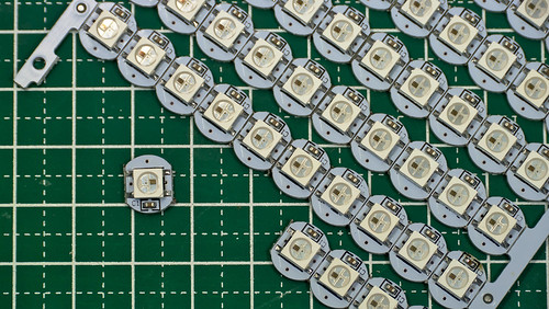
Using such LEDs makes wiring up a vehicle very easy: one only needs to run 3 wires from one LED to the next.
Also the control electronics becomes simpler as only a simple low pin-count device is needed.
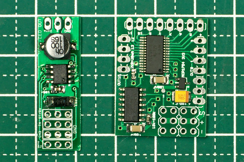
WS2812 light controller on the left: just 4 components needed. On the right is the previous design using the TI TLC5940 chip.
The WS2812B is extremely cheap too. When ordered in 100 pcs quantity from China it is only slightly more expensive than a regular 5 mm white LED from the local hobby shop.
The WS2812B are SMD LEDs in a 5 x 5 mm square case. This makes mounting them in a traditional RC car light bucket, which is usually designed for 5 mm round dome style LEDs, inconvenient.
However, the PL9823 has the same functionality as the WS2812B and comes in a standard 5 mm dome encasing with four leads. The PL9823 is timing compatible with the WS2812B, so both LEDs can be mixed in the same string of lights.
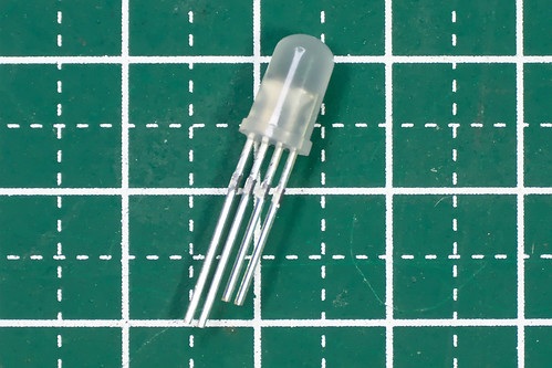
The PL9823 has few downsides over the WS2812B:
- High power consumption of ~7-8mA even if the LED is off.
- When power is applied the LEDs usually light up blue until they receive valid data. The WS2812B stay off until data is received.
- Data format is red-green-blue , while WS2812B is green-red-blue. This can be easily dealt with in software though.
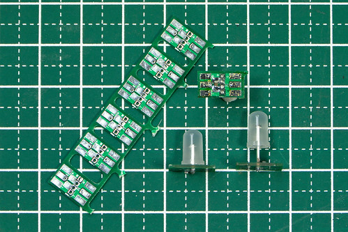
When using the WS2812 it is advisable to not buy the bare LED, but rather the ones that come on a tiny circuit board of ~10 x 10 mm. This board already contains the bypass capacitor and convenient terminals for soldering.
Unfortunately no such board seems to exist for the PL9823. It is possible to solder wires directly onto the leads of the LEDs, but due to the narrow pitch it is not fun. We have made a small break-out board, including bypass capacitor, ourself.
Compared to the light controller design using a TLC5940 chip, the narrow operating voltage range of the WS2812B or PL9823 based light controller is certainly a downside. The WS2812B can operate between 3.5V to 5.3V, the PL9823
requires 4.5V to 6V. The PIC12F1840, a small 8-pin microcontroller, we are using can operate between 2.5V and 5.5V.
This means that the light controller is best powered from a 5V BEC, or if the BEC operates at 6V a diode must be used to drop the voltage to the safe range.
The LEDs also do not tolerate any reverse voltage. When + and - are accidentally swapped they burn out immediately. Don't ask how we know...
A great feature of the WS2812B or PL9823 based light controller is that the color of each LED can be programmed individually. In our Rally Legends Lancia Fulvia body shell the rear indicators and reversing lights are driven by a single LED, but by programming the LED to output either white or orange light we were still able to simulate reversing lights and indicators.
Unfortunately there does not seem to be any variant of the WS2812B or PL9823 that comes in a 3 mm dome factor, which is sometimes used in light buckets of Tamiya or HPI. Maybe with such a body the TLC5940 based light controller will be a better choice.
As with all our current DIY RC Light Controller iterations, firmware and hardware files are available for download on our Github page. Based on feedback from other users, we have also added pre-compiled HEX files for certain configurations as well as improved the documentation.
have fun with RC!
laneboysrc- Crawler
- Posts : 877
Join date : 2012-05-21 -
Re: Laneboysrc - DIY Light controller system
![]() by boolean21 Wed 20 Aug 2014 - 17:43
by boolean21 Wed 20 Aug 2014 - 17:43
So that's what you had been busy with?
Great work bro!
boolean21- Crawler
- Posts : 5035
Join date : 2011-08-18
Location : Deep inside the Jungle -
Re: Laneboysrc - DIY Light controller system
![]() by babyboy Thu 21 Aug 2014 - 1:08
by babyboy Thu 21 Aug 2014 - 1:08
babyboy- Crawler
- Posts : 721
Join date : 2011-09-28
» Winch controller for RC systems
» [TRANSMITTER MOD] HobbyKing HK310 AUX channel hacking - by LaneboysRC
» Crawlers help! LED system
» Crawler Brashless Combo System
|
|
|